- 您现在的位置:买卖IC网 > Sheet目录3832 > AT87C52X2-3CSUM (Atmel)IC 8051 MCU 8K OTP 40MHZ 40DIP
23
TS8xCx2X2
4184I–8051–02/08
are received simultaneously, an internal polling sequence determines which request is
serviced. Thus within each priority level there is a second priority structure determined
by the polling sequence.
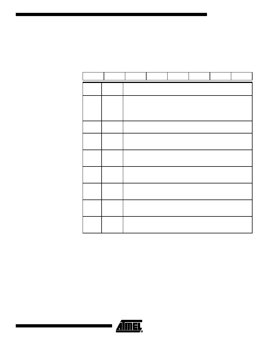
Table 12. IE Register
IE - Interrupt Enable Register (A8h)
Reset Value = 0X00 0000b
Bit addressable
7
6
5
4
3
2
1
0
EA
-
ET2
ES
ET1
EX1
ET0
EX0
Bit
Number
Bit
Mnemonic
Description
7
EA
Enable All interrupt bit
Clear to disable all interrupts.
Set to enable all interrupts.
If EA=1, each interrupt source is individually enabled or disabled by setting or
clearing its own interrupt enable bit.
6
-
Reserved
The value read from this bit is indeterminate. Do not set this bit.
5
ET2
Timer 2 overflow interrupt Enable bit
Clear to disable timer 2 overflow interrupt.
Set to enable timer 2 overflow interrupt.
4
ES
Serial port Enable bit
Clear to disable serial port interrupt.
Set to enable serial port interrupt.
3
ET1
Timer 1 overflow interrupt Enable bit
Clear to disable timer 1 overflow interrupt.
Set to enable timer 1 overflow interrupt.
2
EX1
External interrupt 1 Enable bit
Clear to disable external interrupt 1.
Set to enable external interrupt 1.
1
ET0
Timer 0 overflow interrupt Enable bit
Clear to disable timer 0 overflow interrupt.
Set to enable timer 0 overflow interrupt.
0
EX0
External interrupt 0 Enable bit
Clear to disable external interrupt 0.
Set to enable external interrupt 0.
发布紧急采购,3分钟左右您将得到回复。
相关PDF资料
PIC16C924-04/L
IC MCU OTP 4KX14 LCD DVR 68PLCC
PIC16F767-I/SO
IC PIC MCU FLASH 8KX14 28SOIC
PIC24FJ64GA310-I/PF
MCU 16BIT 64KB FLASH 100TQFP
DSPIC33FJ64GP202-E/MM
IC DSPIC MCU/DSP 64K 28-QFN
PIC16F876A-I/ML
IC MCU FLASH 8KX14 A/D 28QFN
PIC16F876A-I/SO
IC MCU FLASH 8KX14 EE 28SOIC
PIC16F876A-I/SP
IC MCU FLASH 8KX14 EE 28DIP
AT87C51RD2-3CSUM
IC 8051 MCU 64K OTP 40MHZ 40DIP
相关代理商/技术参数
AT87C52X2-3CSUV
功能描述:8位微控制器 -MCU Microcontroller
RoHS:否 制造商:Silicon Labs 核心:8051 处理器系列:C8051F39x 数据总线宽度:8 bit 最大时钟频率:50 MHz 程序存储器大小:16 KB 数据 RAM 大小:1 KB 片上 ADC:Yes 工作电源电压:1.8 V to 3.6 V 工作温度范围:- 40 C to + 105 C 封装 / 箱体:QFN-20 安装风格:SMD/SMT
AT87C52X2-RLRUM
功能描述:8位微控制器 -MCU 0.5um RoHS:否 制造商:Silicon Labs 核心:8051 处理器系列:C8051F39x 数据总线宽度:8 bit 最大时钟频率:50 MHz 程序存储器大小:16 KB 数据 RAM 大小:1 KB 片上 ADC:Yes 工作电源电压:1.8 V to 3.6 V 工作温度范围:- 40 C to + 105 C 封装 / 箱体:QFN-20 安装风格:SMD/SMT
AT87C52X2-RLTUL
功能描述:8位微控制器 -MCU C72X2C52 0.5m OTP RoHS:否 制造商:Silicon Labs 核心:8051 处理器系列:C8051F39x 数据总线宽度:8 bit 最大时钟频率:50 MHz 程序存储器大小:16 KB 数据 RAM 大小:1 KB 片上 ADC:Yes 工作电源电压:1.8 V to 3.6 V 工作温度范围:- 40 C to + 105 C 封装 / 箱体:QFN-20 安装风格:SMD/SMT
AT87C52X2-RLTUM
功能描述:8位微控制器 -MCU C72X2 C52 0.5 m X 2 OTP 0.5 NV RoHS:否 制造商:Silicon Labs 核心:8051 处理器系列:C8051F39x 数据总线宽度:8 bit 最大时钟频率:50 MHz 程序存储器大小:16 KB 数据 RAM 大小:1 KB 片上 ADC:Yes 工作电源电压:1.8 V to 3.6 V 工作温度范围:- 40 C to + 105 C 封装 / 箱体:QFN-20 安装风格:SMD/SMT
AT87C52X2-RLTUV
制造商:ATMEL 制造商全称:ATMEL Corporation 功能描述:8-bit Microcontroller 8 Kbytes ROM/OTP, ROMless
AT87C52X2-SLRUL
功能描述:8位微控制器 -MCU Microcontroller RoHS:否 制造商:Silicon Labs 核心:8051 处理器系列:C8051F39x 数据总线宽度:8 bit 最大时钟频率:50 MHz 程序存储器大小:16 KB 数据 RAM 大小:1 KB 片上 ADC:Yes 工作电源电压:1.8 V to 3.6 V 工作温度范围:- 40 C to + 105 C 封装 / 箱体:QFN-20 安装风格:SMD/SMT
AT87C52X2-SLRUM
功能描述:8位微控制器 -MCU Microcontroller RoHS:否 制造商:Silicon Labs 核心:8051 处理器系列:C8051F39x 数据总线宽度:8 bit 最大时钟频率:50 MHz 程序存储器大小:16 KB 数据 RAM 大小:1 KB 片上 ADC:Yes 工作电源电压:1.8 V to 3.6 V 工作温度范围:- 40 C to + 105 C 封装 / 箱体:QFN-20 安装风格:SMD/SMT
AT87C52X2-SLSUL
功能描述:8位微控制器 -MCU OTP C52/8K 40MHZ 3V COM RoHS:否 制造商:Silicon Labs 核心:8051 处理器系列:C8051F39x 数据总线宽度:8 bit 最大时钟频率:50 MHz 程序存储器大小:16 KB 数据 RAM 大小:1 KB 片上 ADC:Yes 工作电源电压:1.8 V to 3.6 V 工作温度范围:- 40 C to + 105 C 封装 / 箱体:QFN-20 安装风格:SMD/SMT